- 您现在的位置:买卖IC网 > Sheet目录507 > SGP23N60UFTU (Fairchild Semiconductor)IGBT W/DIODE 600V TO-220-3
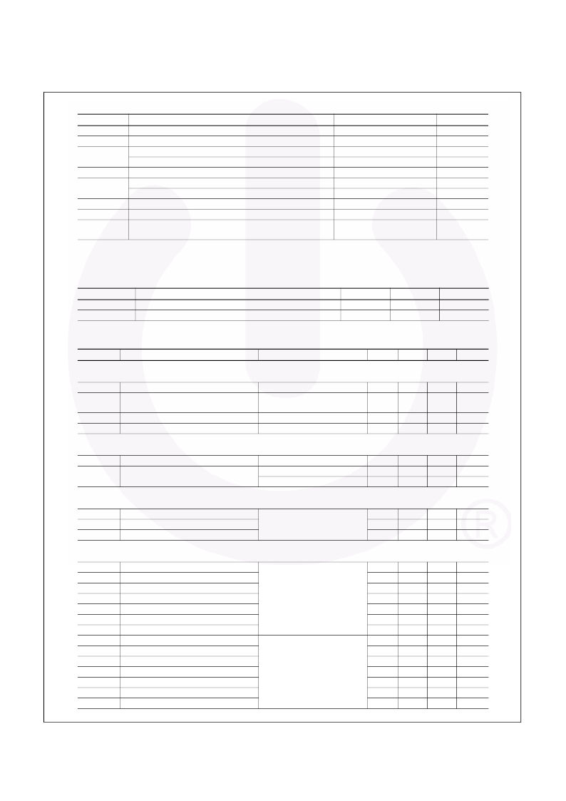
Absolute Maximum Ratings
T C = 25 ? C unless otherwise noted
Symbol
Description
Ratings
Unit
V CES
V GES
I C
I CM (1)
P D
T J
T stg
T L
Collector-Emitter Voltage
Gate-Emitter Voltage
Collector Current
Collector Current
Pulsed Collector Current
Maximum Power Dissipation
Maximum Power Dissipation
Operating Junction Temperature
Storage Temperature Range
Maximum Lead Temp. for Soldering
Purposes, 1/8” from Case for 5 Seconds
@ T C = 25 ? C
@ T C = 100 ? C
@ T C = 25 ? C
@ T C = 100 ? C
600
? 20
23
12
92
100
40
-55 to +150
-55 to +150
300
V
V
A
A
A
W
W
? C
? C
? C
Notes :
(1) Repetitive rating : Pulse width limited by max. junction temperature
Thermal Characteristics
Symbol
R ? JC
R ? JA
Parameter
Thermal Resistance, Junction-to-Case
Thermal Resistance, Junction-to-Ambient
Typ.
--
--
Max.
1.2
62.5
Unit
? C / W
? C / W
Electrical Characteristics of the IGBT T
C
= 25 ? C unless otherwise noted
Symbol
Parameter
Test Conditions
Min.
Typ.
Max.
Unit
Off Characteristics
BV CES
? B VCES /
? T J
I CES
I GES
Collector-Emitter Breakdown Voltage
Temperature Coefficient of Breakdown
Voltage
Collector Cut-Off Current
G-E Leakage Current
V GE = 0 V, I C = 250 uA
V GE = 0 V, I C = 1 mA
V CE = V CES , V GE = 0 V
V GE = V GES , V CE = 0 V
600
--
--
--
--
0.6
--
--
--
--
250
± 100
V
V/ ? C
uA
nA
On Characteristics
V GE(th)
G-E Threshold Voltage
I C = 12 mA, V CE = V GE
3.5
4.5
6.5
V
V CE(sat)
Collector to Emitter
Saturation Voltage
I C = 12 A ,
I C = 23 A ,
V GE = 15 V
V GE = 15 V
--
--
2.1
2.6
2.6
--
V
V
Dynamic Characteristics
C ies
C oes
C res
Input Capacitance
Output Capacitance
Reverse Transfer Capacitance
V CE = 30 V , V GE = 0 V,
f = 1 MHz
--
--
--
720
100
25
--
--
--
pF
pF
pF
Switching Characteristics
t d(on)
t r
Turn-On Delay Time
Rise Time
--
--
17
27
--
--
ns
ns
t d(off)
t f
E on
E off
E ts
t d(on)
t r
t d(off)
t f
E on
E off
E ts
Turn-Off Delay Time
Fall Time
Turn-On Switching Loss
Turn-Off Switching Loss
Total Switching Loss
Turn-On Delay Time
Rise Time
Turn-Off Delay Time
Fall Time
Turn - On Switching Loss
Turn - Off Switching Loss
Total Switching Loss
V CC = 300 V, I C = 12 A,
R G = 23 ? , V GE = 15 V,
Inductive Load, T C = 25 ? C
V CC = 300 V, I C = 12 A,
R G = 23 ? , V GE = 15 V ,
Inductive Load, T C = 125 ? C
--
--
--
--
--
--
--
--
--
--
--
--
60
70
115
135
250
23
32
100
220
205
320
525
130
150
--
--
400
--
--
200
250
--
--
800
ns
ns
uJ
uJ
uJ
ns
ns
ns
ns
uJ
uJ
uJ
?1999 Fairchild Semiconductor Corporation
SGP23N60UF Rev. C1
2
www.fairchildsemi.com
发布紧急采购,3分钟左右您将得到回复。
相关PDF资料
SGPD.12A
EVAL KIT GPS SGP.12A ANTENNA
SGPD.15A
EVAL KIT GPS SGP.15A ANTENNA
SGPD.18C
EVALUATION KIT FOR SGP.18C
SGPD.25C
EVAL KIT FOR SGP.25C
SGS10N60RUFDTU
IGBT W/DIODE 600V 10A TO-220F
SGS5N150UFTU
IGBT SWITCHING 1500V 5A TO-220F
SH8J62TB1
MOSFET P-CH DUAL 30V 4.5A SOP8
SH8J66TB1
MOSFET P-CH DUAL 30V 9A SOP8
相关代理商/技术参数
SGP2-500-BS
制造商:Banner Engineering 功能描述:SGP2-500-BS PAIR 2 BM GRD W/PIGTAILS 500mm EZ SCREEN
SGP2-500-BS20
制造商:Banner Engineering 功能描述:SGP2-500-BS20 PR 2 BM GRD W/PIGTAILS 500mm EZ SCREEN
SGP2-584
制造商:Banner Engineering 功能描述:SAFETY, SGP2-584 PAIR 2 BM GRD 584MM EZ SCREEN
SGP2-584Q88E
制造商:Banner Engineering 功能描述:LIGHT SCREEN; SAFETY; EZ-SCREEN; 2 PNP, OSSD; 8 PIN EURO QD; RANGE .8-20MM
SGP25C
制造商:未知厂家 制造商全称:未知厂家 功能描述:GPS SMT Patch Antenna
SGP25D
制造商:未知厂家 制造商全称:未知厂家 功能描述:GPS SMT Patch Antenna
SGP30-2.5K
功能描述:AIR QUALITY GAS SENSOR FOR VOC'S 制造商:sensirion ag 系列:- 零件状态:在售 类型:空气质量 精度:±10% 输出:I2C 工作温度:-40°C ~ 85°C 电压 - 电源:1.62 V ~ 1.98 V 电流 - 电源:48mA 标准包装:1
SGP30N60
功能描述:IGBT 晶体管 FAST IGBT NPT TECH 600V 30A RoHS:否 制造商:Fairchild Semiconductor 配置: 集电极—发射极最大电压 VCEO:650 V 集电极—射极饱和电压:2.3 V 栅极/发射极最大电压:20 V 在25 C的连续集电极电流:150 A 栅极—射极漏泄电流:400 nA 功率耗散:187 W 最大工作温度: 封装 / 箱体:TO-247 封装:Tube
